Archive for the ‘Uncategorized’ Category
Breathing Room
After stuffing everything inside, there needed to be a place for the air to go so I just left the top ‘game insertion’ slot open, with the fan near the holes where the original video connections were. But, it was still getting quite hot in some areas when I put my hand on the top. So the next logical step was to put the ventilation in.
However, as I was prepping for the ventilation, the bottom piece I had hot glued on popped up on one side. I had anticipated this might happen in my last post, as has been my experience with hot glue before. I also came to the realization that if the bottom piece were to pop off, the metal hard drive could come in contact with the underside of the motherboard – and that would be bad. So I removed the whole thing – some spots were very difficult, mostly the areas where there was a bit of roughness in the plastic from other things I had removed. I then re-did the piece and used sandpaper to rough up the whole area on the NES case and the acrylic piece I was putting in where they would come in contact and be glued. And this time I used epoxy. So it should hold quite well.
Note to anyone trying to remove hot glue: Rubbing alcohol works wonders! It made even the toughest parts come off with a little work.
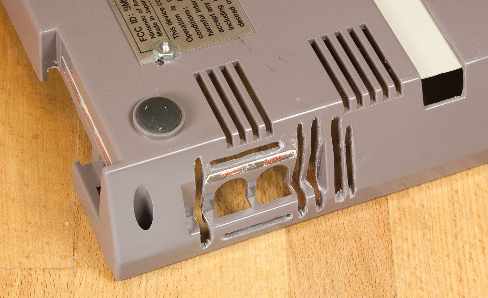
I measured a pattern and drew lines on the inside of the case where I will be putting all the fan holes. Then I got the dremel, and had at it. It’s not the prettiest of holes, but here’s what the results look like:
Exhaust holes:
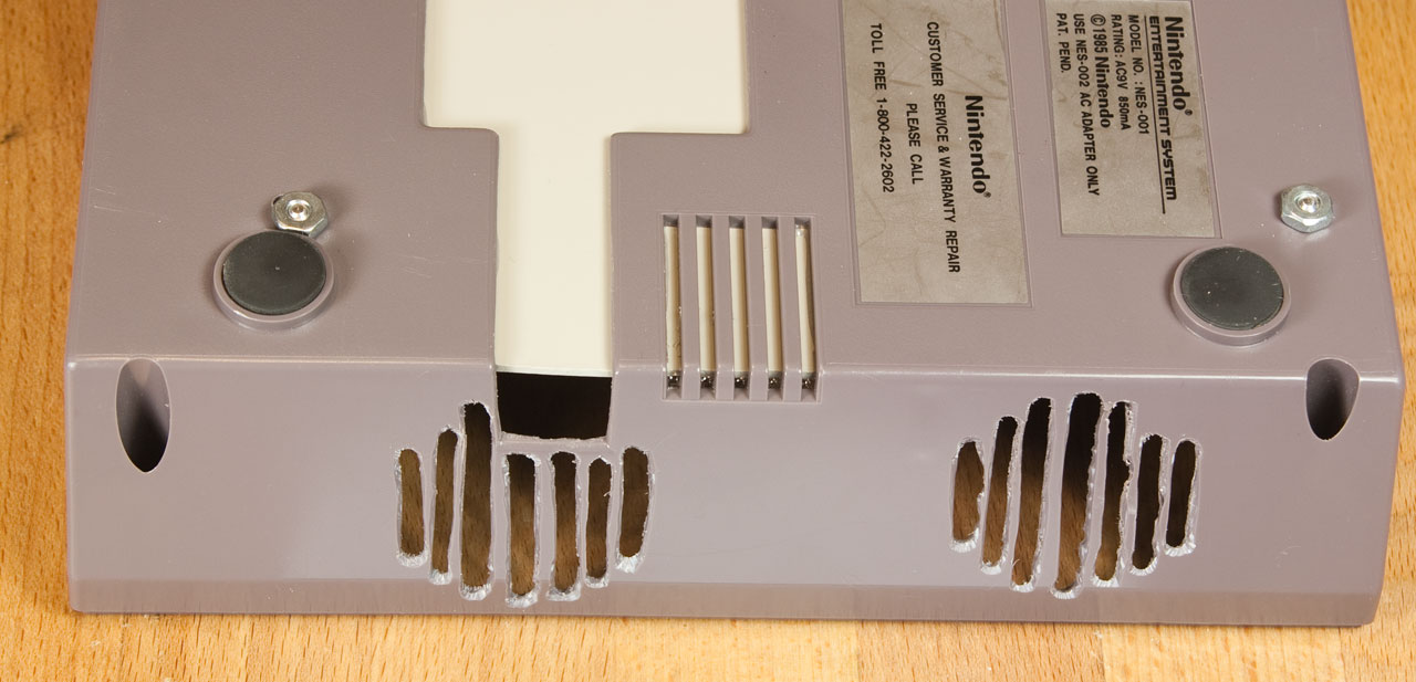
Intake holes:
While I had everything open, I decided to fix the LED light as well. I previously had to cut a hole in the power LED/power/reset circuit board in order to mount the motherboard, and this disconnected the power LED. I was going to just solder wires directly to the LED leads, but I realized I could pretty easily fix the board with just a single wire. I scratched off part of the mask on the board to reveal the copper traces, and then just soldered a wire going from the LED around the hole to it. The left side is without the wire, the right is with:
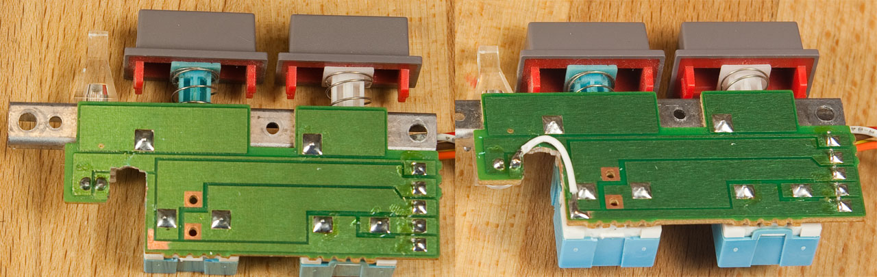
Now I can just use the connector as normal. And I did, I reconnected the LED to the motherboard so it once again lights up when powered on.
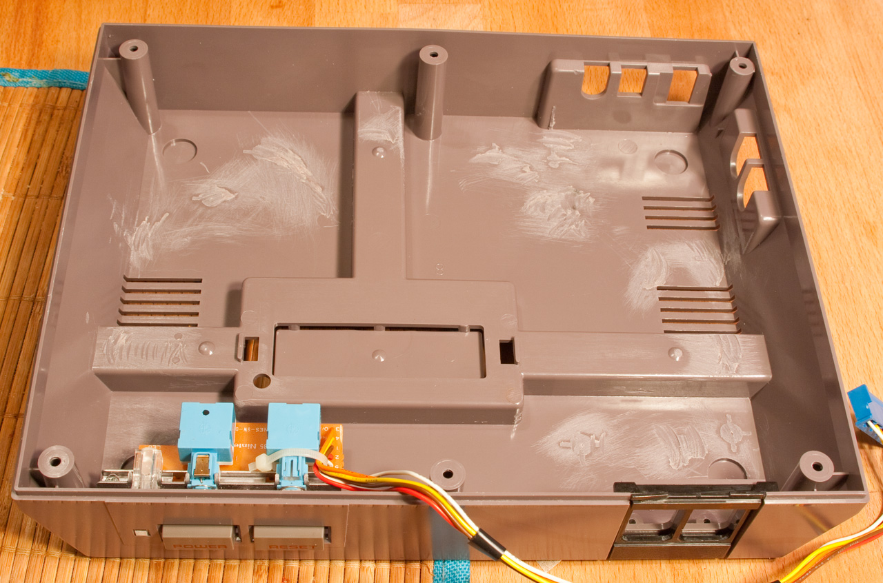
Lastly, I attached all the fans using simple Velcro, and figured out where all the wires would be going. Here is a shot of the inside of the case showing everything in place except the motherboard, and you can see where all the wires run underneath it. The only thing missing is the USB hub and Teensy, which will go in the lower right area of this picture:

Now it runs cool. The only downside is it is louder than I expected. The CPU fan seems quite noisy – a lot louder than when the top is off. But I believe it is not spinning any faster, it is just echoing through the case. I will have to confirm this, and if it is so, my choices will be either to get a similar sized quieter aftermarket cooler, or just live with it.
It fits!
Just when I got started going again, the company I worked for went bankrupt, and that brought things to a halt while I spent my time looking for jobs and brushing up for interviews. But that’s all in the past now, and recently I’ve got my inspiration firing again. The CES has been sitting behind the entertainment shelf, on the floor, partially exposed for a long time now. Things have flown back there from time to time, but thankfully nothing got hurt. I finally decided to stuff this thing inside the case.
There were two issues getting it in. As can be seen in one of my early images, the NES has a large raised plastic section running across the bottom. That had to go in order to be able to fit the hard drive and other wires underneath the motherboard. So out came the Dremel, and off when the plastic:

To cover the hole, I got a piece of clear acrylic sheet from the hardware store and cut it to size with the Dremel. Man, that stuff makes a lot of mess. The Dremel turns acrylic into cotton candy, so I looked like I was attacked by a spider when I was done. I went to the store with a NES controller in my pocket and found an almost perfect match for the gray color in spray paint – for the top half which is light gray! I realized when I got home and looked at the bottom and remembered it was dark gray. However, I decided that for one, the bottom will be hidden most of the time, and two, the contrasting light gray would probably look better anyway than a close but not perfect match of dark gray.
So I painted the piece and secured it on with hot glue. Looking back, I probably should have used epoxy for strength, but this piece shouldn’t see too much stress. And if it does come off, I’ll just epoxy it back on. Here it is attached, from top and bottom:


That took care of the first problem of stuffing things inside. The second problem is it wouldn’t fit, and couldn’t be held in the correct place with mounting standoffs, until the hole was cut in the back for the motherboard backplate. I only got one chance at this. If I screwed up the NES case, the only options were to live with it or start over with a new NES. So I carefully made a pattern of the backplate size. I then tested using this pattern on a piece of the left over acrylic. I then accidentally threw this pattern away when I was cleaning up that night. So the next night I made, and tested, yet another pattern. I made sure not to throw it away.
Now I was ready. I traced my pattern on the back of the NES, carefully attempting to align the position to the correct height and location of the motherboard sitting inside. It straddles the top and bottom half, so I did the bottom first. I erred on the side of too small, and kept checking the backplate and fine tuning it. Then I did the same with the top. Finally, I lined up the motherboard, drilled holes for the standoffs, and put it all together. It worked! And it looked pretty good too. And then, as I was sticking some other stuff in there, I realized a huge oversight – I had put the motherboard (and therefore the hole in the back) in the wrong place.
I had forgotten awhile back, that I mentioned in a post a year and a half ago, that I determined that the reset button could stay as long as I removed a section of the power/reset/LED board and put the mounting standoff right through that board. Well, I had that little board out so I could line everything up and forgot there was only one place that standoff could go. And I didn’t put the backplate hole where that standoff would line up there.
VERY lucky for me, I was only about 1/4 to 1/2 inch off of where it should be. Phew. After a lot of mulling over of options such as moving the hole 1/4 inch over and trying to figure out how to fill the gap, I realized that I could just rotate the motherboard slightly and get that standoff to be in an acceptable spot. This meant that the backplate was no longer parallel with the back of the case. The motherboard is too deep inside the case by about 1/8 inch on one side. But it still doesn’t look too bad, and its a lot better than trying to move the hole over. I also had to drill new holes (leaving extra holes on the bottom) for the new standoff locations. Here is a picture of the power/reset/LED board with the standoff going through it. The removed section means I will have to connect directly the LED leads to power it instead of the wires at the other end of the board. As you can see, it must go here and can’t be moved to either side or it would go through the reset switch or the power LED or the rubber foot on the bottom of the case.

Next is a picture with most things stuffed inside and the motherboard mounted. I have yet to Dremel some holes for the fans and secure them in. I’ll figure out final wire routing when everything is inside (still missing the Teensy internal controller and connections, and the USB hub).

The hard drive is attached to the bottom underneath the motherboard with Velcro. I picked up this trick from a robot we built at the robotics company I worked for a few years back. You just have to be careful not to cover any hard drive holes 🙂 Lastly, here is the back with the top on and screwed in. The front looks just like any other NES, which is the idea.

The power connector is hanging out the back because I haven’t drilled a hole or decided where to mount it yet. But, for now, the CES is actually portable!
Failure and Success
Well, in one sense, I have failed. Caleb had finally reached the point where if the CES was complete, he could use it. And it wasn’t there. I thought I had more time before he got to this point, but I guess he’s growing up too fast. He was able to play Excitebike, Fisher Price Firehouse Rescue, and even a little bit of Super Mario Bros., but I would have to close the game and load up the next one every time he wanted to switch.
But, this sparked a mad rush of many late nights of coding and lost sleep working on the core CES software, but I’m proud to say, I have succeeded and it is now in a state usable by Caleb! Here’s a screenshot of the main screen:

The CES acquires all the joysticks in the system, so Caleb can use the NES gamepad to navigate and choose a game. Once a game is selected, it releases all the joysticks and then launches the emulator for that game, in full screen mode. A background service then sits and waits for the emulator executable to exit, at which point it returns to this main screen and re-acquires all the joysticks.
But Caleb also needed to be able to switch games. I originally planned to use the Reset button on the front of the NES to exit a game. But because the computer is not fully built yet, and Caleb might press the Power button instead at this age, I bought a simple push button and connected it instead with a long cord coming out by the front of the TV. What did I connect it to? Why, another Teensy of course! This teensy will sit inside the computer and connect to all the buttons on the NES case (the Reset, plus more I plan to add for things live saving and loading game state). This Teensy is not a joystick, but rather a standard keyboard. When the button is pushed, the Teesny sends a Control-Alt-Shift-R keypress like any other keyboard, and my software watches for this and automatically closes the running application (emulator). So Caleb can choose a game, play it, and push the button to close it and pick another game all by himself now.
I had to add one more thing to this version. Caleb has been playing flash games on Nick Jr.’s website recently. But this we also had to load for him, scroll the page down to see the game, etc. So I decided to add the functionality to the CES. It’s not much different from an emulator – an executable is launched with the game as the parameter, or in this case a website. So I have it launch Firefox in fullscreen mode to the flash application, and it works beautifully. The ‘Reset’ button closes it too.
There’s just one more thing left. The flash games use a keyboard and mouse to play. So I wrote a special background service that runs when a flash game is launched. It reads input from the joystick (NES Gamepad with Teensy), and translates the up/down/left/right into the arrow keys on the keyboard, and it translates the button presses into the space bar. Fortunately, all the games on Nick Jr. use the spacebar as their button. Pressing the select button on the NES Gamepad switches it into mouse mode, so he can play mouse games too! The arrow buttons on the gamepad move the mouse cursor, and the A button does a mouse click. With some help and practice, Caleb has been able to understand how to switch in and out of mouse mode. That’s pretty good for a 2 1/2 year old!
So, the bottom line is, we can now just turn the application on, give Caleb the gamepad, and he can play and switch between whichever of his games he wants without our help. The biggest problem now is keeping his daily ‘TV Time’ under his 2 hour limit 🙂
Gamepad Teensy Code
I finished the Teensy gamepad code I’ll be using for the gamepads back in January. The base code allows me to very easily configure the number of buttons, the name it shows up as in Windows, and a serial number.
I have made this code available as Open Source for anyone interested at http://robertbyam.com/code
In other news, I’ve successfully written a small library that allows me to find out what USB device is attached to a specific USB port on the computer. I have a small 4 port USB hub that will be inside the computer and plugged directly into the motherboard, and the 4 ports will be on the front of the NES case where the original NES controllers would plug in. I search all USB devices on the system for this specific hub, which I find by the manufacturer and product IDs. I can then tell what is plugged into each of the 4 ports on the hub.
Using this information, I will be able to show at the bottom of the main CES screen what controllers are plugged in, and also show which will be player 1, 2, etc. whenever a specific game is selected, as well as which controllers are disabled because they don’t have enough buttons. This way, it will work similar to the original Nintendo, where the player number was determined by what spot the controller was plugged into.
I built one NES controller with the Teensy inside, and it just barely fits and works well. I also got some SNES controllers off of ebay, and they are thicker, so there will be too much room. I’ll have to glue the Teensy down so it doesn’t rattle around inside.
Teensy 2.0
The Teensy 2.0 showed up in the mail today! Here it is, nice and small:

It took me less than two hours to get a working gamepad in both Windows and Linux. I had found some code online that modified Teensy’s keyboard example to be an SNES gamepad, so a lot of the work was already done. However, the NES and SNES controllers have a chip that communicates over 4 wires to the console using a simple protocol. (I’ll include some fun trivia about the NES/SNES at the end of this post). This code I found used that protocol to communicate with the chip inside the controller. In order to make my gamepads all consistent and not have to worry about timing with the NES chip/protocol, I stripped all of that out and modified it to manually read from the Teensy’s input pins, one for each button.
Once I got it all working, I could plug the USB port in and have a gamepad with 2 axis and 8 buttons (just like the SNES). And I verified that I could use whatever name I want the gamepad to show up as:

The only thing left was to test that it can actually fit inside an NES controller, and it does, sort of. It is maybe 2 sheets of paper too tall, which will probably be okay as long as I can make sure the wires soldered into the holes do not protrude any. Otherwise, I will need to remove the USB connector from the Teensy and solder the USB wires on directly.
Next, I’ll be working on the base code I will use to create each gamepad.
Fun Nintendo Controller Trivia:
The NES and SNES controllers actually use the same exact protocol for communicating with the console. It is very electrically simple, and supports infinite buttons. The console just keeps querying each button until its done. The first eight buttons on the SNES are the same as the NES controller: Up, Down, Left, Right, Select, Start, B, and A. So if you connected the wires of an SNES controller to the NES, it would actually work. The NES queries 8 buttons and then stops. The only downside is the placement of B and A on the SNES controller don’t lend well to pressing the B and A buttons simultaneously with your thumb like you do in Super Mario Bros., etc. The SNES console queries the additional X, Y, L, and R buttons after the first eight.
Case and Controller Solutions
Caleb has started playing Excitebike! That, and I had a week off from from work so I started working on things again.
First, the case. I had previously thought that the motherboard was not going to fit without removing the RESET button from the front of the NES. I thought it was off by about 1/8 inch or so, because the top just barely wouldn’t close, and looking inside I saw the processor fan right up at the top so I figured it wouldn’t work. While trying to calculate how low I needed to go, I discovered that there is indeed room, and it was actually a piece of the inside of the top that was bumping up against the DVI connector on the back of the motherboard. I removed that piece on the inside, and it just barely closed! So I get to keep the RESET button. Everything now just barely fits.
One thing I had not foreseen that I also just discovered, is I can’t mount the motherboard where I wanted it at the far side. This is because the mounting standoffs would be going through the existing rubber feet on the bottom of the NES. I’ll have to move it over a little bit, and that cramps all the room allocated for the fans, power supply, and cords. After a lot of mucking around with this ‘puzzle,’ I believe I finally found a way to stuff everything in there and route the cords.
Now about the controllers: previously I thought I would have to use different solutions for every type of controller, as one chip in all controllers meant I wouldn’t be able to tell them apart. Well, when I was searching for a very simple single USB button to connect the RESET button to, I came across a microprocessor that I think will solve all my troubles: The Teensy 2.0. At $16, it is only $1 more than I paid for the JoyWarrior (today the JoyWarrior is $4 less). But the JoyWarrior also required a few extra components, and tested my patience soldering everything together in such a small space.
The Teensy is a C programmable microprocessor that comes with libraries and sample code to fully support USB. On top of that, it’s extremely easy to load firmware on and use. The JoyWarrior required no programming, but fortunately, coding is something I’m good at. Using their examples, I can easily create my own “gamepad” base program. Then, from the base program, I simply have to add whatever buttons I need, and can even add analog sticks, analog triggers, etc. The best part is, I can name how the gamepads show up in Windows, for example, “CES NES-pad,” “CES SNES-pad,” CES Genesis-pad,” etc. With names like these, I can pop up a message when an SNES game is started saying to plug the controller in if no compatible controllers are already in. I can also map every button just how I want it. This way there will be no need to re-configure buttons on the NES emulator for an SNES gamepad, because SNES Y and B will be the same Windows buttons as NES B and A, respectively.
The other great thing about Teensy is it requires no other components, and the button inputs can be configured to use pull-up resistors. I had to scratch all the pull-up resistors off from the NES gamepad for use with the JoyWarrior. With the Teensy, all I have to do is connect one wire from power, ground, and each button hole on the NES board to a much easier to solder hole on the Teensy (my biggest headache with the JoyWarrior was trying to solder the wires to its pins).
Another Teensy will also live inside the case and connect to the RESET button. This one I will probably program to show up in Windows as a keyboard, and when the button is pressed it will send something like Ctrl-Alt-Shift-X, which my menu software will use to close the current full-screen emulator and return to the games menu.
My Teensy is on its way in the mail – I’m looking forward to playing with it.
NES Controller conversion
Alright, I uploaded all the pictures for this a year ago right before my computer’s hard drive crashed. I successfully converted one original factory NES controller to be USB with a 9 foot cord. Here’s the details:
I opened up the NES controller to see what I was dealing with. There were standard button pads, a chip, and connections for NES wires:


After inspection and testing, I found that there are actually resistors on the board itself – basically just a bunch of resistive material in chunks on the board. These resistors appear to be pull-up resistors, making the voltage going into the chip high whenever the button is not pressed, and then low when the button is pressed. You can see 4 of them (out of 8 resistors for 8 buttons) here:

The JoyWarrior chip I’m using calls for open connections (not connected) when the button is up, and closed when down. So to be safe, I scratched all of these off with a miniature standard screwdriver:

Next, I removed the chip and wires connecting the factory cord:


Then, I simply re-created the circuit I prototyped on the breadboard earlier in as small of a space as I could. This took a lot of time, and partially because my soldering iron tip was getting very old and was difficult to work with. Vertical space was very limited, so I had flatted out the pins on the JoyWarrior chip and was trying to solder the wires directly to the chip pins. There was a lot of frustration getting that solder to flow, especially in such a small space! I now keep an extra tip stocked at home at all times. Here’s the completed circuit, without button connections:

All that was left was then 1 wire for every button, plus 1 ground, from the chip to the NES circuit board. When it was all in place, I put in in the controller and flattened as much as I could. There is a bit of pressure which holds the chip still when the back is screwed on, so I didn’t need to glue it or anything. Here it is just before screwing the back on:

And it works pretty well! I have occasionally noticed some buttons take a bit more pressure than others to activate. I have seen a “gamepad restoration” tutorial online that says this normal wear and tear can be made like new by gluing small pieces of aluminum foil to the buttons, so I may give that a try at some point.
This controller conversion really was a lot of work. I may just get one of the online USB replicas for the second controller, at least initially to see how it works and feels.
Current Status
Well, it has been over a year since my last post. I was in the thick of it when my primary computer’s hard drive crashed. I had just finished one complete NES controller conversion with the JoyWarrior chip and done some other case work, and then the only other computer in our house became unusable. I was considering getting a new computer, and decided if I was going to re-install everything, it was best to do it only once. I also had a friend’s wedding photos that needed to be done and had to wait for the tax refund to come in to get the new computer. All of this, combined with Caleb becoming more and more social, sort of derailed everything. However, since then, the CES has been used in our living room as a general purpose computer for web browsing, Netflix, etc., and has been working great.
I will post shorty the NES controller conversion I had done. Now about the case – I had purchased some standoffs to mount the motherboard onto inside the case. I picked a size that would put the board just above the NES Power/Reset switch board. Unfortunately, they are just barely too high. I tried re-arranging all I could, but it looks like the Reset switch is going to have to be sacrificed in order to fit everything in and get the top on. (UPDATE: It actually does fit, see “Case and Controller Solutions”) I was planning on using the Reset switch as a way to exit out of whatever full screen game was being played and get back to the game browser. But I guess I will have to do something else, like mount a simple button somewhere, or maybe I can hook the Reset button to some other internal button, but the factory button and mount is just too big and in the way.
I don’t have as much free time as I once did, but I will continue to work on this project as I have time. Caleb is 18 months old now, and really won’t be using it for games until he’s at least 3 or 4, so I have some time 🙂
JoyWarrior
I’ve run into a bit of a dilemma with the gamepads. I want to be able to just automatically configure each emulator for whatever gamepad is plugged in at the time, and also be able to disable emulators if a non-compatible gamepad is plugged in. For example, with the SNES controller, you can play either SNES games or Nintendo games. But you can’t do it the other way around because the NES controller does not have enough buttons to play SNES games. I’m planning on building 6 controllers, using 2 more standard out-of-the-box controllers, and then the Wii controllers. I’ll build 2 NES, 2 SNES, and 2 Genesis controllers. The 2 out-of-the-box controllers will have 2 analog sticks each and be used for the N64 and PS2 emulators, and Wii can be for both the Dolphin emulator and NES.
The automation is necessary for Caleb, or anyone, to be able to use it easily. If I don’t do this, then before you can play a game, you’ll have to go into the set up and configure what buttons map to up, down, left right, B, A, etc. This is just too much of a hassle. When its all automated, it will be set up when the emulator launches. The correct button on the controller will be already mapped to the correct emulator button, and it will just work. For example, if you launch the NES emulator but have the SNES controller plugged in, it will change the NES emulator settings to use the button in the closest position to the NES controller to be used.
However, in order to be able to do automatic configuration, I need to be able to tell what controller is plugged in, and that’s where I’m running into trouble. All of the gamepads and chips I have looked at do not have serial numbers. So if I used one type of store-bought gamepad, or one type of chip, for all 6 I’m building, there would be no way to tell which one is which when plugged in. (UPDATE: I have found a better solution to this problem, see “Case and Controller Solutions”)
So, what I’ll have to do is build each of the 3 different types in 3 different ways. For NES, I’m going the pure method: real NES controllers converted to USB. For SNES, I’ll probably get replicas that are already USB with similar authentic feel (but not exact), and for Genesis I can just use a cheap store-bought gamepad and rip out its internals and put them inside the Genesis controller. This way each type will have a different USB Vendor ID and I can tell them apart.
I ordered a joystick chip – the JoyWarrior – to try it out in hopes it would have a serial number (other chips from the same company do). It didn’t, but I still can use it for the NES controllers. I got the chip, and it has a very simple circuit. I dug through my spare electronics parts and found a suitable capacitor and resistor, dug out my breadboard, and put the circuit together. I found an extra USB cord and cut one end off. Then, I plugged it into the computer, and there it was – a new joystick found. I simply connected a loose wire from the chip’s pins to ground one at a time to test the buttons. Here is the breadboard all set up:

Here’s a close up of the JoyWarrior chip:

I also got the NES controllers in the mail. I found them on ebay for $5 each. These are real, used, original NES controllers. I hooked up the old original Nintendo board again to test the controllers, and they both work great. They’re a little bit dirty, so I’ll have to open them up and fully clean them.

The spare components I had (capacitor and resistors) are much bigger than they need to be, so I’ll pick up smaller ones at the store and then figure out how I’m going to build the circuit and stuff it in.
An Evening of Soldering
Usually, when you buy a computer case it comes with all the necessary wires and connectors to hook up everything to the motherboard. Well, in my case (haha), I’m making a custom case. No wires or connectors included, so I have to make them all. So I spent an evening putting a bunch of stuff together.
First off, the power switch cable. There’s a header on the motherboard to connect the power switch, so I need 2 wires to connect to 2 of the pins. Since I already have a tool to crimp such style female connectors, that’s the way I went. I was going to use a pre-made 2-pin connector (sort of like a jumper, but not connected) but I wasn’t able to find any. Here is the female connector by itself:

So, a wire goes in and then gets crimped on. My obsessive-compulsive tendencies had me also sealing the deal with a bit of solder:

Next, I put some heat shrink tubing on. Since these pins will be close to each other, this insulates them from accidentally touching each other:

I did this to 2 wires. And I also had the great idea to put the 2 wires together as one unit. But how? I grabbed one of the 3-pin headers I got for the fans, and put the 2 wires on 2 pins. This held them in place while I covered them in hot glue to fix them together:

Perfect! They were now stuck together with exactly the correct spacing! One final thing left: shave off the excess hot glue with a razor blade so that the connector will fit next to others, and place a heat shrink tubing around the whole thing. Now, I used a simple candle to shrink the tubing. Little did I realize at the time that heat is also what melts hot glue. So as soon as I started shrinking the tubing, the hot glue holding the connectors in place melted, and the heat shrink tubing squeezed them together. Some fast action getting the scissors in between the 2 and then heating some more and placing back on the fan header managed to salvage them, although they’re not quite perfectly straight anymore. Oh well, they fit on nicely at least. Here’s the final wire:

The other ends of the wire will connect to the NES power switch. The NES switch stays in when you push it and keeps the connection. I’ll have to modify it by removing a small piece so it is the same as the Reset switch because this is how current motherboards work. You push the button once, and it comes back out.
The motherboard also has a header for a power indicator LED, so I also need to make wires for this. This time, I think I’ll just leave them separate and connect the 2 wires separately instead of trying to fuse them together like this with the correct spacing.
Next up, the fans. The fans have 3 pin headers – one is power +, another power -, and the last is for the motherboard to sense the RPMs and report the speed (for variable speed fans). The motherboard can also vary the speed through a fourth pin based on temperature, but these fans don’t have that feature. Also included with the fans is an adapter to hook the fan straight up to the power supply through a molex connector (the same one used to connect power to the old style hard drives and DVD drives, etc.). The trouble is, the motherboard only has a connector for one fan, and the power supply only has 1 molex connector. Now, I could buy a few molex splitters, but these are somewhat bulky (almost an inch square) and the splitters would add a couple inches of wiring each, making a big mess of wires and bulky connectors inside an already space-limited case.
So, I made a custom wiring harness for the fans. On one end, it hooks up to the molex connector to get power straight from the power supply. Then, it splits out into 3 very short fan connector wires, and also has another molex connector, so I don’t lose that by connecting up the fans. This way I can use it if I ever decide to add a DVD or Blu-ray drive. And, the wires I used are very short so there won’t be a big mess. Because I don’t need speed sensing, I only needed to connect 2 wires to each fan for power. Here’s the final harness:

I tried hooking it up, and everything works! Woo hoo!
On another, unrelated note, Katamari Damacy was mentioned again in a recent xkcd comic. So I had to see about a PlayStation 2 emulator. Sure enough, there is one, and Katamari Damacy played great at 800×600 resolution! I played through the first 4 levels or so. Now, I’ll have to see if my brother still has all his old PS2 games and wants to give them to me.
I never got too much into the PlayStation side of games, and as such I don’t really know of enough good games I like to want to get the emulators. The emulators I’ve chosen are pretty much for the games I remember playing. I’ll have to go through my brother’s PS1 and PS2 collection to see if there’s anything there I want to put on the CES.
The next logical step I believe is to start trying to put this stuff into the NES; figuring out where everything will go and how it will be mounted. Here we go . . .